Cultivated the design process for structural engineers for over 30 years with the presence in over 150 countries supporting multiple languages.
• Fast and reliable answers to everyday building issues
• Supports a wide range of workflows, integrations, and services
• Large number of design codes, including legacy
• Detailed calculation reports
Short cool demo clips
Shop Here
- Analysis Bundle
- Composite Bundle
- Concrete Bundle
- General Design Bundle
- Geotech Bundle
- Full Structural Set
- Steel Bundle
Do you have any questions for us?
The determination of the effects of loads on physical structure and their components.
Below are the modules included:
The Analysis Bundle (B01) consists of 5 products
The Steel Bundle ( B02) consists of 14 products
Concrete Bundle Software:
The Concrete bundle consists of 11 products
General Bundle Software:
The General Bundle ( B07) consists of 7 products
Composite Bundle Software: consists of 4 products
The suite comprises a number of modules for analysis stability and determining capacity.
Below are the modules included:
The General Bundle (B05) consists of 8 products
Integrates with third-party software to address various workflows.
Below are the modules included:
The Structural Integration Bundle ( B06) consists of 9 products
An Up-Close of the Modules
Sumo is PROKON®’s flagship analysis tool and the centre of the PROKON universe. The program is a three dimensional graphical modelling and analysis tool. Sumo performs frame and finite element analyses of structures. With Sumo you can build 3D models of structures using physical structural components such as beams, columns, and slabs. With its grasp of industry standard file formats, Sumo sits comfortably in the modern BIM process.
Frame performs frame and finite element analyses of 2D and 3D structures. It can perform linear, second order, stage, and non-linear static analysis as well as, buckling, modal, harmonic, and seismic analyses of 3D models. Frame is easy to learn and simple to use. Build your model using a combination of beams, shells, and solid finite elements. Analysis results can be exported to various other PROKON® modules for design purposes. The design links include steel member and connection design, timber member design and reinforced concrete design. Results can be viewed and added to a Calcsheet, both in graphics format and analysis reports. Frame also links to other software by way of DXF, DWG, CIS/2 and SNF (Strucad) files. Frame models can also be exported to and imported from Autodesk® Revit® using Prodesk.
The Plane Stress module can be used to perform finite element analysis of a membrane of any general geometry subjected to plane stress or strain. You can combine simple polygons to model complex geometries, and the program automatically generates a suitable mesh for the analysis. Multiple load cases comprising point loads and UDL’s can be applied to the outline of the model.
The Single Span Beam module can be used to analyse a beam quickly. The beam can be a single span beam, or a single span taken from a continuous beam with the appropriate end conditions. The analysis results of steel beams can be post-processed with the steel member design module for combined stress.
Elastic Support Beam was developed for rapid analysis of a beam or a slab on an elastic foundation. This module allows for the analysis of beams or slabs with varying cross-sections along their lengths. Elastic foundations may include variations or gaps in the elastic medium, and rigid supports. An unlimited number of loads may be entered.
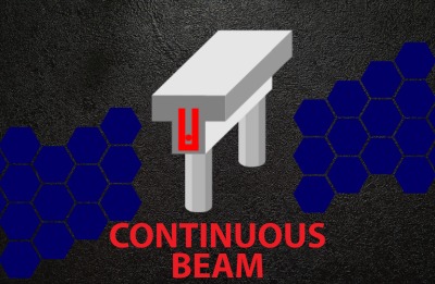
Design single and multi-span reinforced concrete beams and slabs, with rectangular, T, L, or I shaped, and inverted T and L-sections, as well as tapered sections. You can analyse sub-frames and the module automates the pattern loading of dead and live loads at ultimate limit state. Continuous Beam allows redistribution of moments and shear to a user specified percentage. This module can be used on its own or as a post-processor for Sumo. Generate complete bending schedules for beams and slabs.
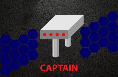
Captain (Computer Aided Post Tensioning Analysis Instrument) designs most types of continuous prestressed beam and slab systems from single span to twenty-spans, encountered in typical building projects. Cross sections can include a mixture of rectangular, I, T and L-sections as well as user defined sections and tapered sections. The module automatically applies pattern loading to entered dead and live loads. At ultimate limit state, moments and shears are redistributed to a specified percentage. Captain can calculate estimates for quantities and tendon profile schedules can be generated for use with Padds. Schedules can be edited and printed using Padds
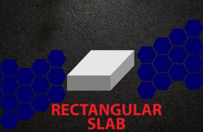
Design rectangular reinforced concrete flat slab panels with a variety of edge supports. You can enter multiple load cases comprising of point loads, line loads, and UDLs, and combine these with ULS load factors. The module calculates steel reinforcement using the formulae stipulated in the relevant design codes. Reinforcement is automatically added to the slab
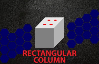
Rectangular Column designs solid rectangular concrete columns subjected to axial forces and bi-axial bending moments. The simplified design approach set out in most codes is used for the design. The module can be used independently, or as a Design Link from Sumo. The Design Links automate data entry by linking analysis results and geometry with the design module
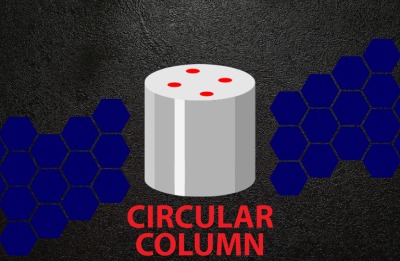
Circular Column designs solid circular concrete columns subject to axial forces and biaxial bending moments. The simplified design approach set out in most codes is used for the design. The module can be used independently, or as a Design Link from Sumo. The Design Links automate data entry by linking analysis results and geometry with the design module.
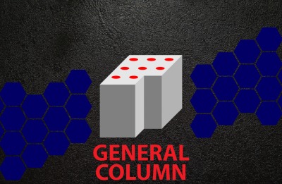
General Column designs columns with any general shape. Rather than using the simplified design approach set out in most codes, General Column designs the column section from first principles.
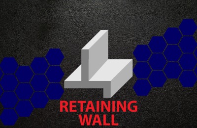
Analyse concrete retaining walls for normal soil and surcharge loads. The module can design most conventional retaining walls, including cantilever, simply supported, and propped cantilever walls. Analyse walls with complex geometries like backward or forward sloping walls as well as walls that have a varying thickness through their height. Optionally include a toe in the base. Choose between the Rankine and Coulomb theories and incorporate seepage in the analysis. A water table can also be specified
Padds, short for Parametric Drawing and Detailing System, was developed specifically for structural engineers and their draughting personnel. With its intuitive and uncomplicated interface, new users can be productive within the first couple of hours of using the program. Without the bloat of modern CAD systems, all that remains is a lean and powerful tool for drawing and structural detailing.
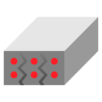
Design reinforced concrete sections to meet specific crack requirements. Both rectangular beam and slab sections can be designed to resist the effects of axial tension, bending moment and temperature and the combination thereof. Temperature effects are also included to evaluate early cracking and long-term thermal cracking. The module accounts for concrete shrinkage due to hydration by a combination of the thermal expansion coefficient and the restraint factor. The design method employed by the codes is ideally suited for non-temperate regions like Europe.
The Beam Section module is a simple utility for designing concrete sections for combined bending, shear, and torsion. The module accommodates rectangular and T-sections. The single input table makes it quick and easy to enter the section geometry and ultimate loading
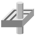
Design reinforced concrete flat slabs for punching shear at internal, edge, and corner columns by specifying the distance from the support to the slab edge; the module automatically determines the shear perimeters. You can enter the amount of longitudinal reinforcement present at the critical perimeters, in the two main directions. The design output gives the critical load case with corresponding amounts of punching shear reinforcement needed for each perimeter, as well as suggested reinforcement configurations and detailed calculations.
Padds, short for Parametric Drawing and Detailing System, was developed specifically for structural engineers and their draughting personnel. With its intuitive and uncomplicated interface, new users can be productive within the first couple of hours of using the program. Without the bloat of modern CAD systems, all that remains is a lean and powerful tool for drawing and structural detailing
Probar 2D is an add-in for Autodesk® AutoCAD® that turns it into a fullly featured reinforced concrete detailing system. Probar 2D offers similar functionality to PROKON® Padds, only in the AutoCAD environment.
Prodesk makes BIM possible – it transfers information between Autodesk® Revit® and Sumo.
Pronet is an extension for Autodesk® Civil 3D®, which allows you to add analytical data to pressure network objects; this includes pressure pipes, fittings, and appurtenances. The network is analysed using a modified 64-bit EPANET engine. The analysis is fast and is performed within the Civil 3D environment. After installing Pronet, the easy-to-use ribbon opens directly from the Civil 3D tabs
Prodesk Steel transfers information between Autodesk® Advance Steel® and Sumo.
Bulk upgrade folders containing Revit® Families; Projects; or Templates to the latest Revit version
Assign unremovable watermarks to Revit® content to help protect your intellectual property. The Watermark tool may be used at any time to audit Revit content and verify ownership.
Import and insert/link MS Excel spreadsheets (.xlsx; .xls or .csv) into Revit® Drafting Views without linking to Revit Schedules.
Import Civil 3D® Pipe Networks through LandXML format to generate native Revit® objects within your Revit projects. This is useful for model federation and model coordination.
Perform advanced analyses between two version of the same model. Choose which elements to compare and what tolerances to verify. The change management tool also features a dynamic coordination tool that enables model coordinators to manage model changes and keep track of issues with elements in question.
Manage Navisworks® clashes directly in Revit®, without the need for Navisworks. The tool requires a Navisworks Clash report (generated through Navisworks), after which it enables model coordinators to manage, find, and solve model clashes directly in the Revit environment, using the Clash Navigator.
Extract Revit® warnings into a manageable interface. Useful for model coordinators to solve model issues or perform model audits.
Bishop Slope is used to evaluate the stability of soil slopes. It uses Bishop’s Modified Method of analysis to evaluate the stability of generalised slopes.
Non Circular Slip can be used for the evaluation of the stability of soil slopes. It predicts the factor of safety of general shape surfaces using the non-vertical slice method.
Wedge Analysis can be used for the evaluation of the stability of soil slopes. It calculates the F.O.S for a tetrahedral wedge that may form in a rock
Rock Slope determines the factor of safety of a planar failure in rock
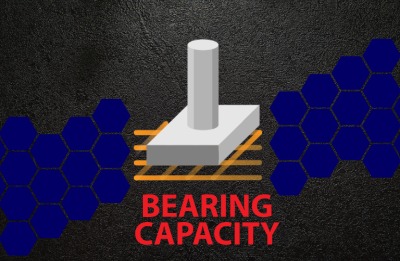
Bearing Capacity evaluates the ultimate bearing capacity of shallow foundations for drained and undrained conditions.
Jointed Rock Masses (Shear strength of jointed rock masses): Most rock masses, exhibit non-linear shear strength/ normal stress failure envelopes, Jointed Rock Masses evaluates this non-linear shear strength envelope for a range of input parameters.
Rock Rough Joints evaluates the shear strength failure envelope for rough joints in rock
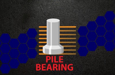
Pile Bearing can calculate the bearing capacity of piles considering the effects of pile length and diameter, installation type and soil conditions.
The calculation of cross-sectional properties of general shapes often involves the solution of equations that require numerical approaches. Prosec uses a finite difference procedure to calculate over 30 bending and torsional section properties
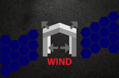
Wind calculates free stream velocity pressures and wind loads on various building geometries.
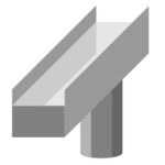
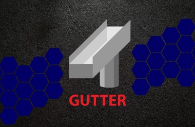
The module designs gutters and downpipes that drain the roofs of building structures.
Masonry Section is used to design reinforced masonry beams that span large openings in walls.
Masonry Wall is used to design various types of load bearing masonry walls.
Masonry Free Wall can be used to verify the lateral load resistance of wall panels away from wall ends.
Strut is used to optimise and design steel members subject to axial stress. The module primarily acts as a post-processor for Sumo and Frame, but also has an interactive mode for quick design checks of individual members without first performing an analysis
Effortlessly design and optimise steel members subject to a combination of axial, bending, and shear stress, e.g., beams and columns in frames. Easily process your analysis results from Sumo and Frame or use the interactive mode for quick design and checking of individual members without the need to first perform an analysis.
Swiftly design and optimise multi-span crane gantry girders with one or two cranes. The program allows for continuously or simply supported girders. Multiple combinations of main beams and capping beams, including standard I-sections, plate girders and box girders are all supported. Crane Beam calculates the envelopes for all the required design forces (including vertical loads and horizontal effects of the moving cranes), moments and deflections.
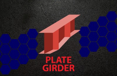
Plate Girder designs I-shaped sections with identical or different top and bottom flanges. The program also allows the user to model tapered elements. The program checks the behaviour of girders under specified loading and gives guidance regarding bearing and intermediate stiffeners. The analysis output can be viewed graphically, or detailed design calculations can be shown.
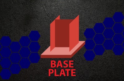
Design column baseplates subjected to axial force and bi-axial moments, as well as shear and torsion. Base Plate can design plates of any general shape that supports steel columns of any shape.
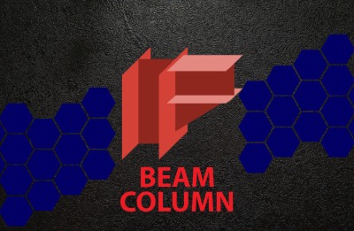
Beam Column is used to design the moment connection between a steel column and beam. The module considers vertical shear, axial compression or tension, and in-plane moment. It facilitates the design of bolted or welded connections and can include a beam haunch.
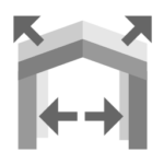
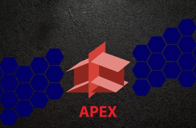
Apex is used to design the moment connection at the apex of a portal frame. The module considers vertical shear, axial compression or tension, and in-plane moment. It facilitates the of design bolted or welded connections and can include haunches.
Hollow Sections performs design checks on welded hollow section joints in lattice structures. The connecting members transmit axial force and can be circular, square, or rectangular hollow sections. The main chord can be I, H, or hollow profiles. Supported connection layouts include K, T, N, X, and Y joints and combinations thereof. The module allows you to enter factored design forces in the chord and braces.
Bolt Group is used to calculate the maximum resistance of a bolt group and determine the smallest bolt size that can be used to resist an in-plane shear force. Both single and double shear cases can be considered.
Weld Group is used to calculate the maximum resistance of a weld group and determine the smallest weld size that can be used to resist an in-plane force with arbitrary orientation
Cleat designs the connection between a beam and a column when axial and shear force is present without bending. The module uses double angle web cleats to transfer forces between beam and column.
Fin Plate designs the connection between a beam and a column subjected to axial and shear forces without bending. The module uses a fin plate welded to the column and bolted to the beam to transfer forces between beam and column.
End Plate designs the connection between a beam and a column subject to shear an axial forces without bending. The module uses an endplate welded to the beam’s web to transfer forces between beam and column.
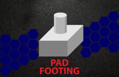
Anchor Bolt allows you to design cast-in headed anchors subject to tension loads. The module can be used as a stand-alone product, or it can be used in combination with the output of Base Plate. The reinforcement layout can be imported from Pad Footing Design.
Timber Beam is used to check and optimise timber members subject to axial and bending stresses, e.g., beams, frames, and trusses.
The beam module allows you to design a composite section for flexure. Composite construction methods are becoming more popular globally due to the rapid construction potential and efficient use of materials. The module forms part of the PROKON structural analysis and design suit together with the three other composite design modules.
The composite continuous beam design module designs multi-span composite beams. Composite construction methods are becoming more popular globally due to the rapid construction potential and efficient use of materials. The module forms part of the PROKON structural analysis and design suit together with the three other composite design modules.
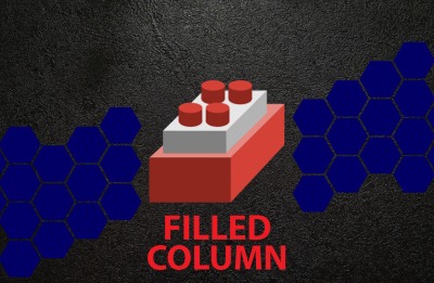
The composite filled column module designs compression members made up of steel and concrete materials. This module considers sections made up of either rectangular or circular hollow sections filled with reinforced concrete.
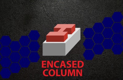
The encased column module designs compression members made up of steel and concrete materials. This module considers rolled steel profiles encased in reinforced concrete.
Innocom has been appointed as an Authorised PROKON Software reseller in the territory of Singapore, Vietnam, Nepal, Hong Kong, Brunei, Burma, Cambodia, Indonesia, Laos, Malaysia, Philippines and Thailand.
Innocom Technologies, as a Technology partner in providing software and hardware solutions across all industries including Construction, Engineering, Private and Government sector for over 28 years collaborating, empowering teams and assisted multifaceted businesses boosting productivity by aligning with current the trend.
We believe our partnership with PROKON adds value to our customers making sure all our buildings and infrastructure are safe to use and in addressing the biggest problems from climate change to disaster relief.


